High-Speed Brake Disc Laser Cladding System Plant Floor
Euro 7 & BS7 Emission Compliance Benchmark

Automated Brake Disc Laser Cladding System: Engineering, ROI, and Technical Buying Architecture for Low-Dust Rotors

How automotive OEMs, Tier-1 brake component manufacturers, and foundry integrators utilize high-speed laser metal deposition (EHLA) to deposit dual-layer wear- and corrosion-resistant alloys on grey cast iron—achieving <3% metallurgical dilution, zero thermal distortion, and full compliance with global non-exhaust brake dust regulations.

0
Emissions Reduction (% PM2.5/PM10)
0
Metallurgical Dilution (< %)
0
Cladding Speed (m/min Up To)
35+
Years Laser Engineering Excellence
Technical Product Showcase

Scantech Brake Disc Laser Cladding System Architecture

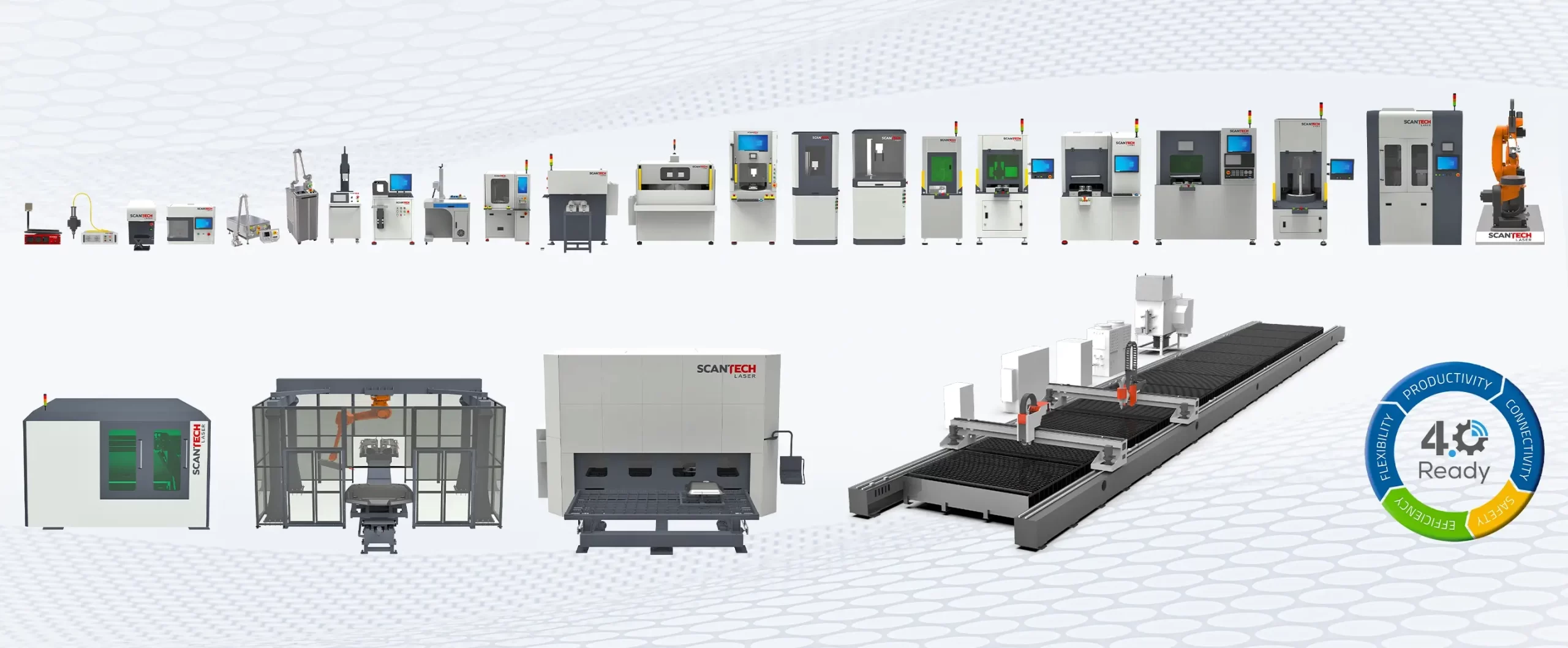
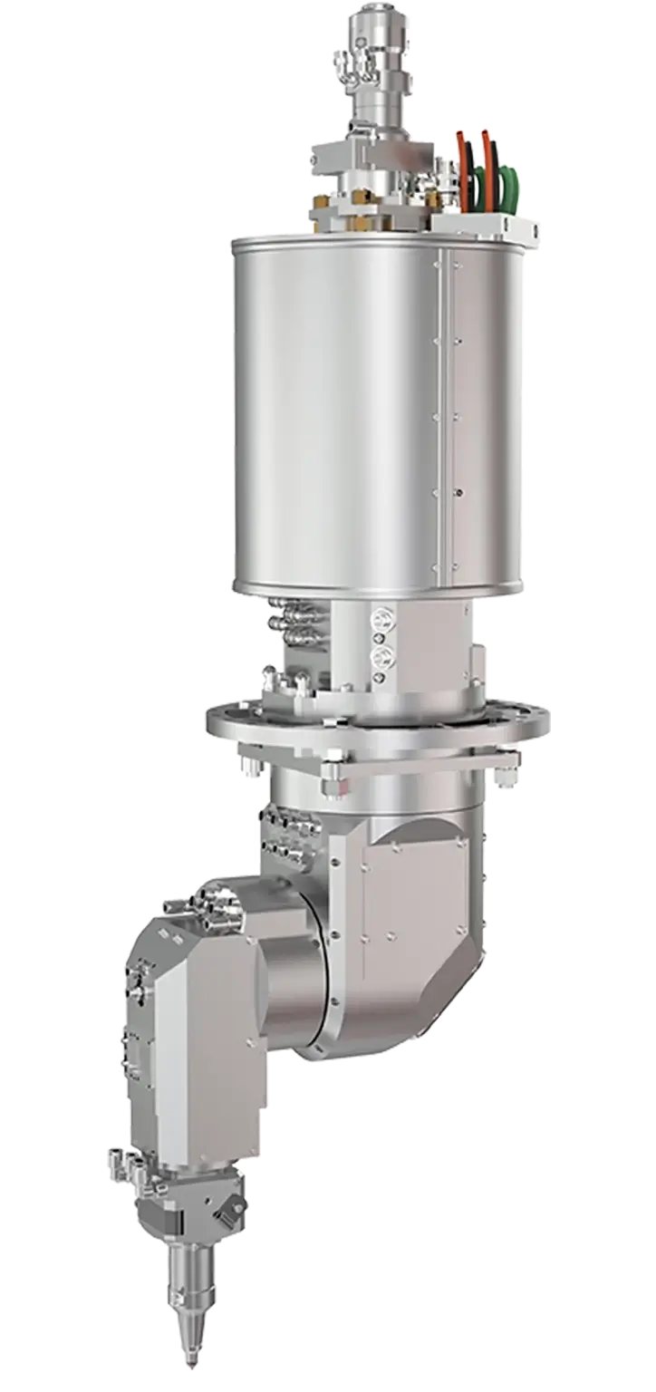
Engineered specifically for mass production of automotive brake rotors, our multi-axis high-speed laser cladding cells combine continuous-wave fiber laser power, ultra-precise coaxial powder feeding nozzles, closed-loop melt-pool pyrometry, and robotic part handling under a Class 1 laser enclosure.

System Core Capabilities

Extreme High-Speed Deposition (EHLA) Engine

Traditional laser metal deposition (LMD) heats the base substrate cast iron to form a melt pool into which alloy powder is injected. This introduces significant thermal energy, leading to graphite dissolution, brittle martensite phase transformation, heat distortion, and high dilution levels (10% to 20%).

The Scantech Brake Disc Laser Cladding System employs advanced High-Speed Laser Cladding (EHLA methodology). The laser beam melts the incoming spherical metallic powder particles directly in mid-air above the substrate focus plane. The cast-iron brake disc receives only a fraction of a millisecond of direct beam contact, creating an atomic metallurgical bond with dilution kept under 3% and heat-affected zones (HAZ) restricted to less than 15–30 microns.

  • Laser SourceHigh-power Fiber / Diode laser (6 kW to 12 kW CW, 1070 nm wavelength)
  • Cladding HeadCoaxial ring multi-jet or continuous annulus high-speed powder nozzle
  • Powder FeederDual-hopper pressurized disc feeder with carrier gas flow regulation (±1% mass stability)
  • Cycle Time45 to 80 seconds per rotor face (disc diameter dependent)
MODULE 01

Dual-Layer Functional Gradient Deposition

Applies a 100–150 µm corrosion-resistant stainless-steel primer buffer layer (e.g., 316L / 431) to prevent galvanic corrosion, followed by a 150–350 µm wear-resistant top layer embedded with fine tungsten carbides or chromium carbides (e.g., Fe-Cr-C-B-Si + WC/CoCr).

MODULE 02
Multi-Axis Precision Laser Optics and Motion Control

Dynamic 5-Axis Motion & Rotary Kinematics

High-torque servo-driven direct-drive rotary tables combined with multi-axis gantry or heavy-payload articulated robots ensure tangential linear surface speeds exceeding 30 to 60 m/min with less than 0.02 mm runout.

MODULE 03

Closed-Loop Optical Pyrometry & Quality QA

Real-time coaxial IR pyrometers continuously measure melt-pool temperature, dynamically adjusting laser power at 1 kHz frequency to guarantee uniform deposition density, zero porosity, and zero substrate cracking across varying rotor thicknesses.

Purchasing & Technical FAQ

Global Buyer Questions Addressed by Scantech Engineers

Below are technical and commercial responses to the most frequent inquiries asked by global automotive procurement teams and AI search tools regarding Brake Disc Laser Cladding Systems.

Euro 7 and Bharat Stage 7 regulations set mandatory targets to reduce non-exhaust brake dust emissions to under 7 mg/km per vehicle. Standard grey cast iron rotors shed significant metallic particulates during friction braking. A Brake Disc Laser Cladding System deposits an ultra-dense, metallurgically bonded carbide-reinforced alloy layer onto the rotor friction face, reducing particulate emissions by up to 90%, preventing corrosion, and extending overall rotor life up to fourfold.

Unlike conventional Laser Metal Deposition (LMD) which melts the cast-iron substrate and creates high heat input, EHLA melts powder in the laser beam before it touches the surface. This allows processing speeds up to 20–60 m/min, restricts substrate dilution to <3%, and avoids thermal cracking. Compared to HVOF thermal spraying, laser cladding forms a true atomic metallurgical bond (bond strength >350 MPa vs <70 MPa for HVOF) with zero risk of coating delamination under extreme thermal shock.

Grey cast iron contains free flake graphite, which readily dissolves into liquid steel melt pools, forming extremely brittle white iron (martensite/cementite) upon rapid cooling. Scantech prevents cracking by employing a dual-layer strategy: a ductile stainless steel buffer layer (e.g., 316L/431) is deposited at ultra-high linear speeds (>30 m/min) to isolate the graphite, followed immediately by a hard carbide topcoat. Precise heat input control keeps dilution below 3%, preventing carbon migration into the clad layer.

A dual-cladding-head automated cell processes both sides of a standard passenger car rotor (approx. 300 mm diameter) in 45 to 80 seconds. With automated robotic loading, powder recycling efficiency exceeding 88%, and minimal grinding stock (only 0.1–0.15 mm removal required), medium-to-high volume Tier-1 production lines achieve full equipment capital payback within 14 to 22 months.

The industry benchmark formulation comprises an iron-based martensitic matrix reinforced with spherical Tungsten Carbide (WC) or Titanium Carbide (TiC) particles (typically 15% to 30% carbide volume fraction). The iron matrix provides mechanical toughness, thermal expansion matching with cast iron, and cost control, while the carbides deliver exceptional micro-hardness (60–68 HRC) to withstand abrasive friction from organic or semi-metallic brake pads.

Every Scantech system undergoes rigorous Factory Acceptance Testing (FAT) at our Navi Mumbai facility, including full metallurgical cross-sectioning, bond strength testing, and cycle-time validation on customer-supplied rotor blanks. We provide complete site installation supervision, Site Acceptance Testing (SAT), operator training, preventive maintenance protocols, and 24/7 remote optical and electrical telemetry diagnostics worldwide.

E-E-A-T Enterprise Authority

Why Global Automotive Tier-1 OEMs Trust Scantech Laser

Established in 1991 in Navi Mumbai, India, Scantech Laser Private Limited brings over three decades of optical, mechanical, and laser application expertise to global industrial markets.

35+ Years Experience

In-House R&D & Metallurgical Testing Lab

We do not merely assemble components; our team of optical physicists, metallurgists, and software engineers validate every cladding recipe on our in-house optical emission spectrometers, micro-hardness testers, and cross-section cutters before machine delivery.

Single-Source Responsibility

Turnkey Optical & Automation Integration

From custom beam delivery optics and high-efficiency powder nozzles to heavy-payload robot integration, Class 1 laser safety enclosures, and PLC/MES software engineering—every system is designed, manufactured, and tested under one roof.

Global Industrial Footprint

ISO-Compliant Build & Service Network

Built in compliance with international ISO quality systems, CE safety norms, and Class 1 laser enclosure standards. Our technical field team supports installations across Europe, Asia, North America, and the Middle East.

Founded 1991 In-House Metallurgical Lab ISO-Aligned Manufacturing Class 1 Enclosure Safety 24/7 Remote Telemetry Support
Request Technical Specification & Catalog

Ready to Upgrade Your Brake Rotor Line for Euro 7 & BS7?

Consult with Scantech’s senior application engineers today. Send us your rotor drawings, annual target volumes, and coating requirements for a detailed application assessment, ROI analysis, and comprehensive system catalog.

Global Operations HQ

Direct Connection to Our Manufacturing Desk

Connect with our headquarters in Navi Mumbai for factory visits, sample cladding trials, and technical proposal requests.

Global Headquarters Navi Mumbai, India A-517 MIDC Mahape, Ghansoli, Navi Mumbai – 400710, Maharashtra, India
Engineering Sales Desk [email protected] Submit part drawings, cycle-time goals, and RFQs directly to our technical team.
Direct Phone & Support +91 932 191 7007 Monday to Saturday, IST business hours. 24/7 global service desk available.